Basics of braking
Jets’ high cruise speeds come with an unavoidable penalty: higher landing speeds. Optimizing a wing for low drag at high indicated airspeeds and Mach typically means that the low-speed characteristics of the wing suffer, raising the stall speed of the aircraft when compared to a propeller-driven airplane of a similar weight. Higher stall speeds, in turn, necessitate higher landing speeds, as most light jets are certified to fly final approach down to 50 feet above the runway at a speed no less than 130 percent of stall speed.
 IIlustration by Kevin Hand
Physics tells us that kinetic energy increases with the square of velocity, so a light jet crossing the numbers at 110 KIAS has nearly double the kinetic energy (assuming weight is constant) of a single-engine turboprop at 80 KIAS. Given that all the light jets in production lack thrust reversers, there’s only one way to dissipate all that energy: the wheel braking system of the aircraft, aided by drag created with ground flaps, ground spoilers, and/or speedbrakes. Understanding the operation and limitations of the brake system is of critical importance to jet pilots.
All of the widely produced light jets in current production use a variation on the same basic brake system: hydraulically powered brakes monitored by an antiskid computer. Most of the designs have an electric pump to generate the needed hydraulic pressure, in some cases dedicated only to the brakes; in others, also generating the pressure needed by the landing-gear system. The other common system design, found in heavier light jets, uses engine-driven hydraulic pumps to generate pressure.
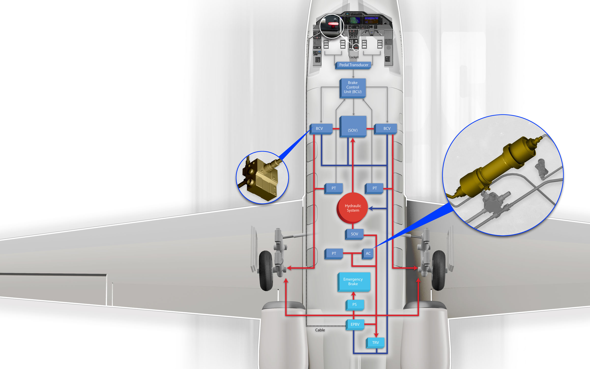
Two schools of design also dictate how pilot inputs via the rudder pedals are transformed into pressure at the brake assembly. The more traditional design features cables that run from the pedals to metering valves near the center of the aircraft. As the pilot presses harder on a brake pedal, the appropriate metering valve opens more, and greater hydraulic pressure is applied to the corresponding brake.
Some recently designed jets feature a “brake-by-wire” system. In this setup, when the pilot pushes on the brake pedals, the movement is measured by a transducer and converted into an electrical signal transmitted to a central brake control unit (BCU). The BCU then electrically commands movement of the metering valves—so there’s no physical connection between the pedals and metering valve.
In all cases, the pressure being applied to the brakes can be reduced as needed by an antiskid computer. Even when landing on dry runways, but especially on wet or contaminated surfaces, the antiskid computer is an essential part of the brake system’s ability to minimize stopping distance. As brakes are applied on the landing rollout, the tire begins to “slip,” or experience a speed slower than that of the aircraft with respect to the pavement. A fully slipped tire is one that is locked: The wheel speed is zero, but the aircraft is still moving.
Some slip is needed to maximize braking force; but too much or too little results in decreased braking. The magic of antiskid computers is their ability to rapidly sample the speed of the wheel and compare it to an optimum deceleration profile. The antiskid computer will then reduce pressure to the brakes as needed to maintain the optimal slip ratio. As a small change in the slip ratio of the tire can result in quite a large change in braking effectiveness, maintaining ideal slip is not a task a pilot can manually perform. For this reason, landing with antiskid inoperative usually requires that 50 to 60 percent more runway be available, even on dry pavement.
The antiskid computer typically has several other jobs in addition to optimizing the slip of the wheel. It will monitor the left and right wheel speeds relative to each other to sense if one wheel has entered a deep skid condition because of contamination on the runway, and release pressure if needed. The computer also knows if the airplane is in the air or on the runway, and it will prevent a tire blowout on landing should the pilot accidentally depress the pedals as the airplane touches down.
With brakes so critical to light jets, redundancy is a must. If the primary hydraulic system were to fail, the pilot needs another method to actuate the brake discs. Again, most backup brake systems fall into one of two design camps.
The first uses an accumulator to trap hydraulic pressure in a subsystem isolated from the main hydraulic system. An accumulator can be thought of as a hydraulic “battery.” It will hold a finite amount of pressure but needs to be initially charged by the main hydraulic system. An inert gas such as nitrogen lies on one side of a piston within the accumulator. When pressurized hydraulic fluid is applied to the other side of the piston, the gas compresses and attempts to push back against the piston and fluid. Close a valve at the outlet of the accumulator and it’s now full of fluid trapped under high pressure, able to exert braking force if needed.
The second emergency brake design uses inert gas itself to apply brake pressure. The nitrogen is inside a bottle plumbed to the main brakes. Pulling a lever in the cockpit opens a valve, which releases pressurized gas to the brake actuators. Here, we’ve simply replaced pressurized hydraulic fluid with high-pressure nitrogen as the means of applying pressure to the brake discs.
Both types of emergency brake systems share one critical element: No antiskid protection is available. Should the pilot be heavy-handed, the tires will lock, and they can be destroyed within seconds by the friction. For this reason pilots are taught to pull the emergency brake handle gently, just until they sense the initial application of the brakes, and only use this minimal force unless it’s clear the aircraft would depart the end of the runway.
Even using the normal brake system requires techniques different from those of piston or turboprop aircraft. Using differential braking at high speed in a jet, for example, is a no-no. The antiskid computer will react more quickly than the pilot, and should the pilot attempt to correct a swerve with brakes—as opposed to rudder—the aircraft can enter a lateral pilot-induced oscillation, darting side to side at an alarming rate. Likewise, if the pilot senses a skid and releases brake pressure, as would be appropriate in a piston, the antiskid system will need to reset and “start over” in its calculations when the brakes are reapplied, increasing stopping distance.
For this reason, pilots are taught simply to apply the brake pressure that’s appropriate to the runway length, up to full pressure if needed, and hold that pedal application until the aircraft reaches taxi speed. The more the pilot does to modulate pressure, the longer the ground roll will be. Modern brake systems are a marvel, and used properly they can stop a 15,000-pound aircraft in less than 2,000 feet of ground roll—as long as the pilot lets them work their magic without unnecessary or counterproductive inputs.
Neil Singer is a Master CFI with more than 8,500 hours in 15 years of flying.

