Turbine Pilot: Pressure Pointers
A brief guide to cabin pressurization
What It Looks Like
Eye locator
By Mark R. Twombly
The positioning of a crew seat in a turbine-powered aircraft is more than a matter of making yourself comfortable. Proper adjustment of the seat fore and aft, and vertically, is crucial to achieve the optimum view outside the cockpit in the most important phase of flight—the final approach and landing.
Over decades of development, design engineers have determined just where that optimum viewing position is in the cockpit. It’s called the design eye reference point, and it’s the precise spot that allows the pilot to observe a length of approach or touchdown-zone lights that would be covered in three seconds at final approach speed—a distance of about 600 to 750 feet. In other words, it’s the ideal eye position from which to observe the final approach.
So how do you know when you’re positioned in your seat at that optimum design eye reference point? Simple—look at the eye locator. It’s the device mounted in the windshield center post that functions as a sighting device to assist the pilot in adjusting his or her seat.
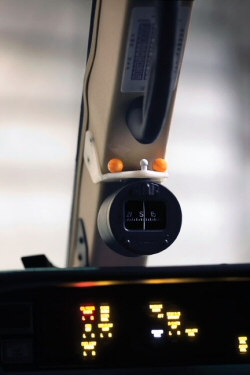 In the accompanying photo of a Cessna Citation 650 cockpit, the eye locator has three ball-type symbols arranged in a triangular shape. This configuration enables both left- and right-seat crewmembers to adjust their seats and head positions for the best inside and outside viewing angles. The optimum vertical and lateral position is achieved when the near (white) ball is in line with, and partially obscures, the far (orange) ball.
The design eye reference point is more than a nice-to-know feature of cockpit design. In 1990, a Beech C99 commuter turboprop crashed in Ontario, Canada, on a night approach. The Transportation Safety Board of Canada (TSB) said the captain had positioned his seat very low, “to facilitate instrument flying, which was clearly at the expense of external visibility.” The TSB found fault with the design of the C99 cockpit in part because there was no way for a crewmember to identify the ideal viewing position. “Without clear reference or guidance regarding where to position oneself in order to optimize external visibility, it is possible to position oneself where one cannot see anything outside the aircraft that is below the horizon,” the safety board concluded.
It pays to spend a bit of time attaining the ideal seat position before lighting the fires. For each inch the eye is located below the design eye reference point, you lose about 120 feet of ground visibility at the base of the windshield.
Mark R. Twombly flies a Citation II and a Citation VII based in Southwest Florida.
Routings
High or low, which way to go?
By Doug Turner
Sometimes we find ourselves flying repetitive routes and the process can get somewhat tedious. We learn from experience how air traffic control will route us, the frequency we can expect next, and when we are about to receive that descent instruction for arrival to the airport. To keep things interesting, though, I often experiment with different tactics, such as asking for higher or lower altitudes to take advantage of the prevailing wind and weather conditions.
Sometimes, however, I’ve learned to leave well enough alone. In the past I tried trading a higher cruise altitude for a lesser headwind at a lower altitude, but eventually concluded that the additional fuel required quickly negates any wind-related advantage.
In the aircraft I fly, a Twin Commander 690 with Honeywell TPE331-10T engines, each 1,000-foot increase in altitude adds a significant plus to the true airspeed. How much? I am always amazed at how well the old two-percent rule of thumb works to compute true airspeed. Here’s how it works: true airspeed generally increases about two percent per thousand feet.
In the Commander, if the indicated airspeed is 200 knots at Flight Level 200, then I can reasonably expect a 40-percent shove (20 in thousands of feet times two percent), or about 80 knots, for a true airspeed of 280 knots. At FL280 I can expect only about 195 KIAS, but 56 percent (28 times two) of 195 indicated is 109 knots, so I get about 304 KTAS. This airplane has an accurate air data computer, and the machine’s calculations correspond closely to the rule of thumb.
If it were only about speed, then the headwinds at FL280 could be 24 knots stronger than the headwinds at FL200 and we would see the same groundspeed, so climbing an extra 8,000 feet would seem pointless. But we know that choosing a cruise altitude is about more than just groundspeed. At FL280 the fuel burn is substantially lower about 400 pounds per hour (pph) total in the Commander versus about 450 pph at FL200. Fifty pounds of fuel, or about 7.5 gallons of Jet A, is not much for a one-hour flight, but the difference can add up quickly over longer flights. Also, I can fly for another seven minutes at FL280 with 50 pounds of fuel and travel another 35 miles.
Most turbine airplanes—jets and turboprops—perform in this fashion.
It is not too often that the winds are so much stronger up high than at the middle altitudes that staying down in those middle altitudes will pay off. Even in jet aircraft, it takes a lot of increase in headwind at the very highest altitudes to justify lower cruise altitudes where the true airspeed is lower and the fuel consumption higher. Besides, above the high 30s the winds typically stabilize and may even decrease in velocity.
So, after consulting all the charts and choosing different cruise altitudes to try all the possibilities, it seems that the fruits of my labor do nothing more than make the time go by a little quicker on those long repetitive flights. But then that was the point, because ATC has just cleared me to start down for landing.
Doug Turner is a retired air traffic controller and supervisor. He is a commercial pilot with experience and ratings in a wide range of turbojet and turboprop aircraft. He owns a Beechcraft Baron and flies a Twin Commander for a Kansas City based corporation.
Turbine Talk: Zero Fuel Weight
Your max payload ends at ZFW
By Thomas A. Horne
Pilots unfamiliar with turbine aircraft may stumble over the term “ZFW,” meaning zero fuel weight. This is a published weight limit that dictates how much fuel you can load after you’ve totaled up the basic operating weight (BOW—the airplane’s empty weight, plus the weight of the crew), plus the weight of your passengers and their baggage. In other words, after you’ve reached your maximum published ZFW, all remaining weight must be in fuel. Obviously, this limits your range, because the bigger your payload, the less fuel you can take on. ZFWs are published to minimize stresses on the wing spar attach points. Too much payload in the fuselage can mean big trouble if there’s too little fuel in the wing tanks: Turbulence-induced up and down forces can make the too-heavy fuselage cause large flexing moments at the wing attach points. Adding fuel after the maximum ZFW weight minimizes this flexing by putting fuel weight outboard of the fuselage. But there is a drawback—your payload maxes out at maximum ZFW. This can come as a shock to those transitioning to turbines, who’ve been accustomed to loading any combination of passengers, bags, and fuel right up to maximum ramp weight. In turbine ops, that’s a definite no-no.
Turbine Flying
What It Looks Like: Eye locator
Routings: High or low, which way to go?
Turbine Talk: Zero Fuel Weight
Turbine News Briefs
Flight Options, Raytheon’s fractional ownership operator, was sold to private equity firm H.I.G. Capital in December. Almost concurrent with the deal closing, Embraer announced a major order from Flight Options for 100 Phenom 300 jets with an additional 50 options. The deal, worth a potential $1.12 billion at current list prices, is the largest Phenom order to date. Deliveries are expected to begin in 2009.
Despite continual delays on its A700 very light jet program, Adam Aircraft recently won type inspection authorization (TIA) for the twinjet from the FAA. The TIA allows FAA representatives to begin flight testing the A700, with credit given toward eventual certification. According to company president Duncan Koerbel, the A700 is on track to achieve certification in 2008.
As a testament to the boom occurring in business aviation, the Aerion corporation’s supersonic business jet concept has received at least 20 $80 million orders to date, all for a concept that has yet to be proven. The initial program launch is scheduled for 2009, with deliveries by the end of 2014.
Silverhawk Aviation is now offering an engine upgrade option for Beechcraft King Air 90 owners. The company’s new STC allows for Pratt & Whitney PT6A-135A engines to be installed on the King Air C90, C90A and E90. Performance upgrades are plentiful, including faster climb rates, and a 50-knot increase in true airspeed, according to Silverhawk.
Hawker Beechcraft’s new King Air B200GT won FAA certification late last year. The newest King Air 200 cruises at a maximum of 305 knots, thanks to new Pratt & Whitney PT6A-52 engines rated at 850 shp. The aircraft is able to seat up to nine passengers in a standard configuration. Typically equipped price is $5.26 million.
An airworthiness directive was issued recently on the Piaggio P 180 Avanti to correct what the FAA said is a problem with the airplane’s longitudinal flight controls binding because of ice. Investigations revealed that fuselage drain holes on the airplane were plugged, trapping water in the lower fuselage; the water froze, temporarily rendering the airplane uncontrollable. Compliance actions include inspection of the drain holes and a maintenance manual supplement.— Ian J. Twombly
Turbine aircraft engines are happiest flying high where fuel flows diminish and true airspeeds increase, but altitude is less friendly to humans. Oxygen that our lungs can extract from the atmosphere decreases with altitude. There are two choices—provide supplemental oxygen through masks, or increase cabin pressure by mechanical means. As the percentage of oxygen in the atmosphere does not vary, the predominant difference between air at sea level and air at six miles aloft is pressure. So all you have to do to maintain adequate body oxygenation at altitude is to increase pressure inside the cabin.
Increasing cabin pressure is accomplished by routing compressed air from a turbine engine stage prior to combustion. This air, called “bleed air,” is hot because it is highly compressed. Considering the inhospitable low air temperatures aloft, this heat is advantageous. Even so, bleed air is way too hot for a cabin environment so it’s passed through a heat exchanger where outside air cools it.
Typically bleed air flow is not adjusted; it freely enters the cabin. To regulate cabin pressure, outflow valves open and close automatically to keep cabin pressures at the level required. This regulation is necessary because you don’t want to exceed the cabin’s rated pressure differential (the difference between the pressure inside the cabin pressure vessel and the outside). And, despite design and manufacturing efforts, it is impossible to build an airtight cabin. There are always door leaks, and air can escape where control cables and other utilities must exit and enter the pressure vessel.
When too much pressurized air leaks from the cabin, the outflow valves close, creating a more air tight cabin and causing cabin pressure to adjust to a proper level. As aircraft systems go, pressurization systems are close to foolproof. As long as the cabin is sealed and bleed air is on, the cabin should pressurize to and maintain maximum pressure differential (the lowest possible cabin altitude). Although flying at the maximum pressure differential is safe, it is considerably more comfortable to schedule cabin pressurization and depressurization. This is the job of the pressure controller.
Aircraft pressurization performance is expressed in pounds per square inch (psi) and is indicated on a gauge with a red line at maximum.
A typical jet flying in the 30,000-foot range can maintain a maximum pressure differential of 8 to 9 psi. This seemingly small pressure results in tons of pressure when multiplied by the large number of square inches of cabin surface. The large hinges and latches of a pressurized aircraft door attest to the forces that must be contained.
However, knowing only the cabin differential does not provide physiological information—cabin altitude, which also is displayed, is a better indicator. Ideally, cabin altitude should be no higher than about 8,000 feet for passenger and crew comfort and safety. FAA-mandated aural and/or visual warnings signal when the cabin reaches 10,000 feet, indicating inadequate pressure or lack of pressurization.
A third key parameter is cabin rate of climb. We humans are most comfortable with rates of climb and descent of 500 feet per minute or less. Faster rates are uncomfortable and can even lead to painfully blocked ears and sinuses, and in extreme cases, incapacitation. A turbine aircraft typically climbs and descends at rates of several thousand feet per minute. The role of the pressure controller is to regulate the cabin altitude and vary the pressure at rates much lower than the aircraft’s altimeter and vertical speed readouts. For example, the cabin climbs to 8,000 feet (taking 16 minutes at 500 feet per minute) while the aircraft climbs to about 40,000 feet (at an average 2,500 feet per minute in the same 16 minutes).
Turbine aircraft have one of two common pressurization control systems. A completely automated system requires the pilot to enter only the destination field elevation. It then does all the scheduling (the timing and rate of cabin climb or descent) without the need for further pilot input. Older systems require the pilot to set the rate of a cabin climb/descent. After takeoff, the controller is set according to cruise altitude, and prior to descent it is adjusted to a level appropriate to the landing field elevation. This setting is usually 500 to 1,000 feet above the airport elevation.
Of course, pressurization scheduling may not be perfect, and it is possible for cabin differential to reach its maximum before cruise altitude is reached. At this point, the cabin climbs at the aircraft’s rate of climb. Usually, this is not a problem, as aircraft rate of climb progressively decreases with altitude and is relatively modest at the top of the climb.
A mismatch on the way down may occur as the cabin descends faster than the aircraft on a shallow descent profile. At some point cabin altitude may be higher than aircraft altitude. However, that does not last long, as the outflow valves tend to equalize this pressure quickly.
If a descent is extremely rapid, it is possible for the airplane to land with residual pressure inside the cabin. Manufacturers defeat this potential problem by incorporating a microswitch in the main landing gear; ground contact activates this “squat” switch, which opens an outflow valve and “dumps” the cabin.
Ian Blair Fries flies a TBM 700. He is ATP, CFII, and LearJet-rated.
Active turbine pilots with story ideas for this section are asked to e-mail [email protected].
Related Articles


