Mentor Matters: Runway analysis
Planning for engine failures is harder then it looks

In a previous article, I discussed the fallacy that jet aircraft may not legally depart IFR unless able to maintain any specified departure procedure (DP) climb gradient following the loss of an engine (“Obstacle Departure Procedures,” May 2013 AOPA Pilot Turbine Edition). While many pilots widely believe this true, the AIM is clear in stating that DPs assume normal aircraft performance with all engines operating. Rather than requiring the ability to fly a DP with an engine inoperative, what is required of operators is that they develop “contingency procedures” to cover the case of an engine failure during or after takeoff.
For-hire operators, such as jet charter providers and the airlines, have the specific requirements of such contingency procedures spelled out in minute detail in Advisory Circular (AC) 120-91. While it is not mandatory for Part 91 operators to follow AC 120-91, it is the only formal guidance available on how to create acceptable engine-out contingency procedures. The AC details for 20 pages the lateral and vertical areas that must be analyzed for obstacles, and how they vary depending on navaids available, turning versus nonturning paths, et cetera.
Because of the sheer number of obstacles present in a typical departure path, no operators but the largest airlines have the capability to perform such analysis in-house. Rather, third-party organizations provide this service as part of a broader package going by the name of runway analysis. Runway analysis rolls several mandated calculations into one easy-to-use, bottom-line number—at what maximum weight can an aircraft take off, meeting all the various performance demands placed upon it by the FAA?
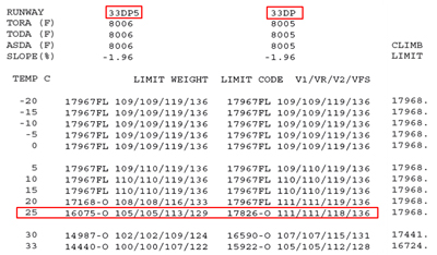
For example, using a runway analysis package (above right), a light jet pilot might determine that departure at 25 degrees C from Runway 33 at Aspen, Colorado, is legal up to a maximum weight of 17,826 pounds. As long as the takeoff begins at or below this weight, all runway, climb, and obstacle clearance performance requirements will be met.
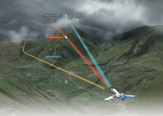
Often the runway analysis provider will also create one or more special departure procedures, to be followed in the event of an engine failure during the takeoff. By utilizing a lateral path that follows the lowest terrain, these special procedures can allow takeoff at weights thousands of pounds higher than what might be possible flying the lateral path of a departure procedure (DP).
There are dragons lurking under these special procedure paths, however, and many pilots are unaware of how close to terrain these operations might take them. Further, they impose additional demands on the pilot that must be carefully thought out before takeoff, to ensure the pilot’s ability to keep the aircraft squarely on the prescribed lateral path.

Perhaps the biggest trap in blindly utilizing runway analysis and/or special departure procedures is how little lateral and vertical separation from terrain is actually provided if operating at the maximum allowed weight. AC 120-91 allows for as little as 35 feet of vertical obstacle clearance following an engine failure, less than the wingspan of even the smallest light jet. Laterally, the area of protection can be as narrow as 300 feet outside the airport boundary, or stated otherwise, one-twentieth of full scale CDI deflection on an RNAV departure.
Further, special departure procedures may be complex to execute, and not loadable from the GPS or FMS. Some require a sequence of headings be flown, with reaching a specified DME serving as the trigger to change heading. Having witnessed hundreds of simulated engine failures in both simulators and actual aircraft, I’ve seen many pilots struggle with just cleaning up the airplane properly and flying precisely at single-engine climb speed (the prescribed V2). To add the stress of needing to manage heading changes based on subtle navigation cues creates a situation that is, frankly, unreasonable for the average single-pilot jet operator.
If the special engine-out departure path diverges from the cleared departure procedure, the pilot must consider how and where a transition to the special procedure could be accomplished. If an engine failure occurs on the runway, it is clear that following the special procedure is required. Conversely, an engine failure several thousand feet above the airport while on the DP will most likely allow the pilot to continue the DP safely, with a large buffer of altitude already underneath the aircraft. But what if the engine fails at 400 feet agl, as the aircraft is starting the first turn on the DP? One thousand feet? Two thousand feet? Depending on how divergent the normal and engine-out paths are, and where the hazardous terrain is, there will be a point where continuing the DP is safer; clearly, in flight isn’t the time for the pilot to be determining this, and careful pre-flight consideration is needed.
The use of runway analysis and/or special departure procedures are a double-edge sword; they are the only practical way for most operators to comply with the requirement to have a post-engine-failure contingency procedure, yet they must not be used without significant premeditation. Fortunately, there are steps pilots can take to stack the deck in their favor when using runway analysis in areas of high terrain.
First, pilots should recognize that unless practiced in a simulator regularly, attempting to use special departure procedures that cannot be loaded intact into the FMS (i.e., those that do not follow exactly the lateral track of an existing DP) is unrealistic for most operators. Using a DP ensures the pilot can follow the same path regardless of if and when an engine failure occurs, as well as providing clear, automatically sequencing course guidance during the climb.
Next, the pilot should remember that even following the lateral path of a DP, if operating at the maximum weight allowed by the runway analysis, the pilot maybe placing the aircraft perilously close to terrain. Consider all the variables that can result in not achieving the optimal single-engine climb: a small variation from the prescribed V2, too much or too little rudder input, engine thrust not set perfectly in a non-FADEC aircraft, just to name a few. Some allowance for these variables does exist; for two-engine jets, the FAA reduces test pilot-achieved climb gradients (termed gross gradients) by 0.8 percent to get the net gradients, which runway analysis providers use to calculate terrain clearance.
For a typical light jet with a single-engine climb speed of 110 knots, a 0.8-percent gradient reduction equates to about a 90 fpm climb rate reduction. It’s not hard to imagine average, panicked pilot technique resulting in well more than a 90 fpm loss of performance, relative to that achieved by a test pilot. Based on this knowledge, it may be prudent for a pilot to determine a weight reduction, below that allowed by the runway analysis, which will be applied if takeoff weight is limited by obstacle clearance requirements. How great a padding the pilot applies might vary with overall aircraft performance, the nature of terrain in the area, and the pilot’s confidence in his ability to maintain the precise lateral and vertical track demanded by the departure.
Neil Singer is a Master CFI with more than 7,200 hours in 15 years of flying.
Super-midsize
Bombardier announces Challenger 350
By Jim Moore
Bombardier aerospace has expanded its business jet line with the launch of the super-midsize Challenger 350, announced recently in conjuction with the new aircraft’s first customer, NetJets. Priced just under $26 million, the Challenger 350 is powered by a pair of Honeywell HTF7350 engines producing 7,323 pounds of thrist each. The flat-floor cabin is designed for comfort and is the widest in its class, Bombardier said. NetJets Signature Series models include a custom-designed entertainment and cabin climate management system, contemporary seats and interior, and a modular galley with single-service beverage machine also designed by NetJets.
“Designed to meet the ever-growing needs of our customers, this new aircraft reflects the feedback received from our existing Challenger customers,” said Bombardier Business Aircraft President Steve Ridolfi.
The “paperless” cockpit is designed to reduce pilot workload, built on a Rockwell Collins Pro Line 21 Advanced avionics suite including synthetic vision, dual inertial reference systems, and weather radar among the features and systems. With canted winglets and fuel-efficient engines, the jet can carry eight passengers 3,200 nm.
The aircraft is in the development stage, with performance specifications still being tested and certified. The company plans to begin deliveries in 2014. Bombardier and NetJets jointly announced the new offering at the European Business Aviation Conference and Exhibition (EBACE).
Email [email protected].


