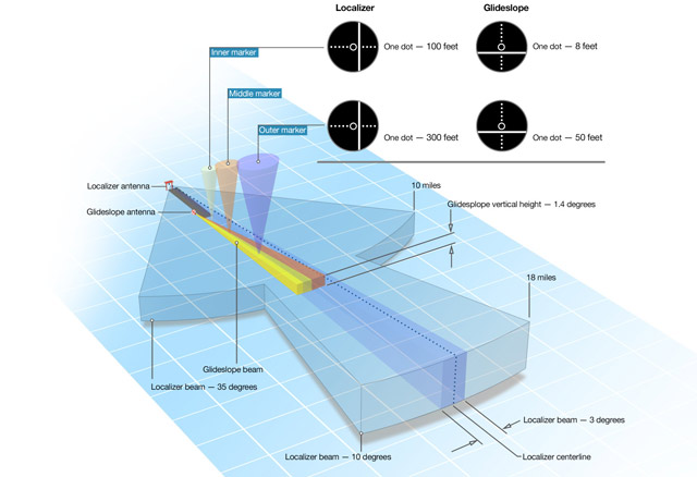
Typical ILS coverage volumes for accurate reception of localizer and glideslope signals. CDI one-dot deflections show the typical signal sensitivities at the outer and inner markers. Compared to the localizer, the glideslope is much more sensitive to deviations from the proper glidepath. The illustration gives general information; signal qualities can vary among ILS installations.
Riding the pipe to 200 and a half
To many instrument-rated pilots, the Instrument Landing System (ILS) approach rates as the gold standard. ILS approaches have been reliably providing precision guidance to hundreds of runways around the world for the past 70-odd years, so when the weather turns seriously rotten it’s the approach that pilots are most apt to request. That’s reason enough for instrument-rated pilots to stay proficient flying ILSs, and for the noninstrument-rated to gain a working knowledge of the basics—just in case.
The big value of the most common Category I ILS approach is its ability to provide both lateral and vertical guidance to runways experiencing weather as low as 200-foot ceilings and/or one-half- mile visibilities. (Actually, the visibility is measured by runway visual range—RVR—transmissometers, which measure visibility along a portion of the runway’s length.) However, those minimums are generalities. Nearby terrain or obstacles can push minimums higher, for example.
Guidance and coverage
The ILS uses paired frequencies to provide an exact approach path for alignment with the runway centerline, as well as precise descent guidance along that path. The localizer part of the ILS signal gives left-right steering commands so you can stay on the signal’s centerline; the glideslope signal gives similar up and down commands. The pilot—and/or the autopilot—responds to these commands by observing course deviation indicator (CDI) deflections and making small heading and pitch corrections so as to keep both localizer and glide slope needles centered. Fly the centered needles “down the pipe,” and you’ll find the runway dead ahead, assuming a no-wind condition. Large crab angles of the sort needed to compensate for healthy crosswinds may require that you look to one side or the other to spot the runway. That’s well worth remembering on windy nights, or whenever visibilities are restricted by fog, rain, or other restrictions.
Localizer and glideslope signals have limited ranges. At most, reliable signals extend as far as 18 nautical miles or so, but that’s only for localizer guidance within 10 degrees of the course centerline. Closer to the runway—out to about 10 nautical miles from the runway—signals are good within 35 degrees of the course centerline. What does this mean? It means that if you are disoriented and outside these coverage areas, you won’t have reliable ILS signals. Or, in the worst case, you may be tricked by false signal “lobes” that mimic inbound-path CDI indications.
Initial procedures
Like all IFR procedures, the key to shooting a good ILS begins with preparation, anticipation, and staying ahead of the airplane. Once you’ve received your approach clearance, tune in the ILS frequency, identify it, check that the marker beacon lights are working, and get ready to intercept the localizer. Often, in areas where there’s adequate radar coverage, the usual drill is for ATC to vector you to the localizer, at a point somewhere outside the final approach fix. (In nonradar and/or nontowered environments, “full” procedures can be the rule, leaving you to navigate to the ILS’ via feeder and initial fixes on your own.)
Take a good look at the approach chart, noting everything—but paying special interest to minimum altitudes. You should have checked during the preflight briefing to learn if any components of the ILS are inoperative. The glideslope may be out, for example, in which case you’ll be shooting a localizer-only approach with no vertical guidance—and thus have to comply with higher minimums. Call up the weather on the AWOS or ATIS frequency, if the airport has one. Otherwise, a quick call to ATC or Flight Watch may give you the latest weather.
Most pilots now have GPS, moving maps, and flight directors/autopilots—all of which provide great safety advantages. Even so, mistakes can happen, and the stakes are high when flying approaches in low ceilings and visibilities. Turn your CDI’s heading card to the inbound course. Although this won’t affect your course guidance (the ILS only emits accurate tracking cues for a single course, quite unlike a VOR’s radials) it helps keep you oriented to the final approach course as you intercept and track inbound to the runway.
By the way, is your primary nav unit in GPS mode? It shouldn’t be, if you’re on vectors. The unit should be ready to receive VHF transmissions from the ILS antenna, so be sure it’s in CDI or VHF mode. Check your unit’s operating manual for specific switching and other procedures. GPS/navcoms don’t have standardized controls or protocols, unfortunately, so it’s up to you to know your equipment inside-out.
Have a second navigation receiver? Great. Use it for tracking and cross-bearing information for any applicable initial approach fix feeder routes, fixes along the final approach course. Having a second nav source set up for guidance on the missed approach is another good idea. You don’t want to be spinning dials when you’re at 200 feet agl, don’t have the runway environment in sight, and are reconfiguring the airplane for a climb on the missed approach procedure.
Make sure your autopilot—if you have one—is in the correct mode, and properly armed for intercepting, capturing, and navigating the ILS. Usually, the procedure calls for flying in heading mode, then arming the approach mode. As the localizer needle begins to center, many newer autopilots will automatically switch from heading to approach mode, then begin tracking inbound on the ILS. If you’re hand-flying, you’ll be making the intercept and flying the ILS all by yourself.
Flying the final approach course
And if you’re hand-flying, workload ramps up once you close in on the localizer. ATC is supposed to give you no more than a 30-degree intercept angle, but if it’s more than that you have to be especially alert when the localizer needle begins to center. The worst situation is perhaps a 90-degree intercept; that’s when you’ll most likely zoom right through the localizer, and the CDI quickly slams to maximum deflection.
Tracking a localizer is nothing like tracking a VOR radial. It’s much more sensitive. At the final approach fix—about five nautical miles from the runway, and where an outer marker or compass locator may be located—each dot’s worth of needle deflection is worth about 300 feet. At the middle marker—about 5,000 feet from the runway threshold, and where minimums usually are reached—each dot is worth 100 feet. (Incidentally, pegged ILS needles inside the final approach fix call for a missed approach, so there’s some real incentive to precisely track the localizer and glideslope.)
As for glideslope needle deflections, they’re even more sensitive to off-path conditions. At the final approach fix, each dot is worth about 50 feet; a mile from touchdown, each dot counts for just eight feet!
This means that keeping the ILS needles centered becomes a matter of careful, small corrections. Once the localizer is intercepted, heading changes must be made in small increments. At the outset, try no more than 5-degree heading corrections when near the final approach fix. On the ILS final segment, 2-degree corrections are usually best when inside the final approach fix. Corrections any greater than this lead to “stitching up” the localizer as you overcorrect one way, then the other—and never keep the CDI centered.
Intercepting and holding the glide-slope’s vertical track can be equally challenging. But first things first. There can be false lobes associated with glide-slope signals, so to avoid tracking them it’s important to intercept the glideslope from below. As a double-check, compare your altitude at glideslope intercept (when the glideslope needle is centered) with the published glideslope interception altitude on the approach chart. If they’re the same, or very close, you’re following the correct glideslope.
Now that we’re established on the ILS inbound, it’s time to devote your full attention to the instruments—especially the localizer and glideslope needles. We’ll talk about how to best manage the transition to a safe landing in the next installment of “On Instruments.”
Email [email protected]
ILS categories and minimums
Category I: 200-foot Decision Height (DH); 2,400-foot Runway Visual Range (RVR)
Category II: 100-foot DH; 1,200-foot RVR visibility
Category IIIa: No DH or DH below 100 feet; RVR not less than 700 feet
Category IIIb: No DH or DH below 50 feet; RVR less than 700 feet but not less than 150 feet
Category IIIc: No DH and no RVR
Specialized crew and recurrent training are required for all ILS approach categories II through III. A single pilot can fly Category II approaches flying a category A airplane (stall speed below 91 knots) in non-revenue operations under provisions of FAR Part 91.193.
All Category III approaches must be flown using coupled autopilots with autoland capabilities. For Categories IIIa to IIIc, autothrottles are required. Category IIIb airplanes can land, then stop on the runway centerline with their autoland features. Category IIIc-approved airplanes can land, stop, then taxi to the gate—all in zero-zero conditions. —TAH