Performance: What matters most
If a performance chart could talk

 Two months ago, my son and I took a trip to Laramie, Wyoming, elevation 7,284 feet msl. Since that is significantly higher than the areas in which we most often fly, the trip presented an opportunity to open my own POH to refamiliarize myself with the calculations needed to ensure a safe flight. I often use an electronic flight bag to make quick work of crunching performance numbers but in doing so, I don’t gain insight into the relative importance of the factors involved with the calculations nor do I learn ways in which I should be skeptical of the output (see “Learning to Call BS,” April 2021 AOPA Pilot). In particular, I opened the POH to read the story of takeoff performance.
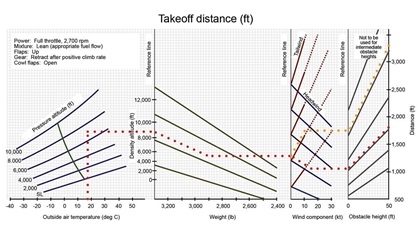
The chart (see Figure 1) features four ingredients in the takeoff distance calculation: atmospheric conditions, aircraft weight, winds, and the presence of obstacles. It assumes that the pilot will adhere to the conditions posted in the upper left: full manifold pressure, 2,700 rpm, flaps up, mixture leaned appropriately for the atmospheric conditions, and retracting the gear as soon as a positive rate of climb is achieved.
Atmospheric conditions. The leftmost panel is simply a density altitude calculator, and I superimposed the corresponding density altitudes to the left of the first reference line. It assumes that you’ve already computed the pressure altitude for the field which is 1,000 × (29.92 - altimeter setting) + field elevation. For example, the day we departed, the altimeter setting was 30.22 in Hg so the pressure altitude was 1,000(29.92 - 30.22) + 7,284 = 6,984 feet msl. Given that engines produce more power at lower altitudes, we got a little help from pressure since the pressure altitude was 300 feet lower than field elevation.
In my own flying, I’ve seen altimeter settings as low as 29.70 and as high as 30.70 and that corresponds to adding 220 feet or subtracting 780 feet from the field elevation respectively to obtain pressure altitude. While lower pressure can hurt performance, those effects pale relative to other ingredients in takeoff performance.
Density altitude is pressure altitude adjusted for nonstandard temperature, which exacts a greater impact on takeoff performance than variations in pressure. The temperature that day was 17 degrees Celsius, about 15 degrees C above standard conditions for the field elevation. That meant our density altitude was almost 9,000 feet msl and the nonstandard temperature added about 300 feet to the takeoff roll.
The panel structure implies that any combination of field elevation, altimeter setting, and temperature that produces the same density altitude will result in the same takeoff performance, other factors being equal.
Weight. The second panel incorporates weight into the calculation of takeoff distance. It makes sense that the line segments slope downward since weight is directly related to takeoff distance. But note that those lines become steeper at higher density altitudes. This means that a given weight addition has a greater impact on takeoff performance at higher density altitudes than at lower altitudes. In other words, if my other son, Pete, had come on the trip with us, the increase in takeoff roll at Laramie would have been greater than at our home airport with a much lower density altitude that day.
Each curve on a graph reveals the way in which, say, climb rate depends on atmospheric conditions and I confess that my inner geek delights in such visualizations.Winds. The slopes of the line segments in the third panel highlight the profound effect of winds on takeoff performance. The 15-knot headwind component we enjoyed shaved 250 feet from our takeoff roll—a 20-percent improvement. Remember to calculate the headwind component and not merely the wind speed. For example, if the winds were 15 knots from a direction 45 degrees off runway heading, then the headwind component would be less than 11 knots. When I am flight planning, I usually plan on calm winds and figure that taking off into the wind will only improve my performance.
The performance charts include information for taking off with a tailwind and I extended those with dashed lines only to emphasize their slopes. The line segments for a tailwind are much steeper in the upward direction than those for the headwind sloping downward. Had we taken off with a 10-knot tailwind, it would have added 500 feet to the takeoff roll alone compared with a no-wind scenario and continued to exact a severe penalty as we climbed away from the airport. The moral of the story is that taking off with a tailwind hurts performance far more than a headwind helps it.
Obstacles. Using the final panel, we expect a ground roll of 1,050 feet and 1,800 feet down the runway, our aircraft should be 50 feet above the runway. Now, this panel makes my BS meter sound for a couple reasons. First, while that extra 750 feet of runway may get us above any of the obstacles adjacent to the runway, it’s good to know that not all obstacles around an airport are just 50 feet high. Many of the trees surrounding my own airport are actually 100 feet high. Second, the panel does not take winds into account. For example, if we had taken off with a tailwind, this panel could greatly underestimate the distance needed to clear a 50-foot obstacle.
To ensure I have the appropriate performance to safely depart an airport, I prefer to use the climb rate performance chart along with the FAA’s Climb/Descent Chart (see “There’s a Chart for That,” February 2019 AOPA Pilot) to make such estimates. The LARAMIE ONE obstacle departure procedure for the airport says that if we can maintain a 200 foot-per-nautical-mile climb gradient and follow the procedure, we can depart with appropriate obstacle clearance.
This takeoff performance chart tells the story of takeoff distance as it is influenced by atmospheric conditions, aircraft weight, winds, and obstacles. Missing components include humidity, engine wear, and my suboptimal piloting technique so it’s important to include a healthy safety buffer. After I calculate a value for required takeoff distance, I always ensure that the runway from which I am departing is at least twice as long as I calculated. It’s a rule that has served me well in my aviation career.
Catherine Cavagnaro is an aerobatics instructor (aceaerobaticschool.com) and professor of mathematics at Sewanee: The University of the South.


